Table of contents
- What is an ASA 150# Flange?
- ASA 150 Class Flange Specifications
- ASA 150 Flange Dimensions
- ASA 150 Flange Pressure Rating
- ASA 150 RF Slip-On Flanges Thickness Chart
- MS Flange ASA 150 PCD Chart
- ASA 150 Class Flange Weight Chart
- Importance of the ASA 150# Flanges
- ASA 150 Standard Flange Application
- ASA Flange Full Form
- ASA 150 vs ANSI 150
- ASA 150 LB flange Advantages
- ASA 150 Flange Standard Disadvantages
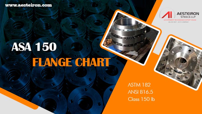
What is an ASA 150# Flange?
The pressure rating of an ASA 150# flange is 150 pounds per square inch (PSI). This specification is based on the American National Standard Institute B16.5 standard and is commonly used for low to medium pressure applications in piping systems. These flanges are designed to ensure a secure connection between pipes, valves, and other components in industrial environments.
ASA 150 Class Flange Specifications
| Class | 150 |
|---|---|
| Size |
|
| Type |
|
| Standard | ASME / ANSI B16.5 |
| Material |
|
| Marking |
|
| Face type |
|
| MTC | EN 10204 3.1/3.2 |
Check dimensions and weight of ASA 150 LB flange
The chart provided below is essential for engineers and professionals working on construction projects. It helps them accurately calculate the weight of the flange, which is crucial for planning and budgeting. Proper weight estimation ensures that the right materials and tools are selected for installation, reducing potential errors and saving time and cost.
ASA 150 Flange Dimensions
| NPS in inch | 1 | 1½ | 2 | 2½ | 3 | 3½ | 4 | 5 | 6 | 8 | 10 | 12 | 14 | 16 | 18 | 20 | 24 |
|---|---|---|---|---|---|---|---|---|---|---|---|---|---|---|---|---|---|
| Dia. of Bolt Circle in inch | 3¹â„₈ | 3â·â„₈ | 4¾ | 5½ | 6 | 7 | 7½ | 8½ | 9½ | 11¾ | 14¼ | 17 | 18¾ | 21¼ | 22¾ | 25 | 29½ |
| No. of Bolts | 4 | 4 | 4 | 4 | 4 | 8 | 8 | 8 | 8 | 8 | 12 | 12 | 12 | 16 | 16 | 20 | 20 |
| Dia. of Bolts in inch | ¹â„₈ | ½ | 5/₈ | 5/₈ | 5/₈ | 5/₈ | 5/₈ | ¾ | ¾ | ¾ | â·â„₈ | â·â„₈ | 1 | 1 | 1¹â„₈ | 1¹â„₈ | 1¼ |
| Dia. of Bolt Holes in inch | âµâ„8 | 5â„₉ | ¾ | ¾ | ¾ | ¾ | ¾ | â·â„₈ | â·â„₈ | â·â„₈ | 1 | 1 | 1¹â„₈ | 1¹â„₈ | 1¼ | 1¼ | 1³â„₈ |
| Flange OD in inch |
4½ | 5 | 6 | 7 | 7½ | 8½ | 9 | 10 | 11 | 13½ | 16 | 19 | 21 | 23½ | 25 | 27½ | 32 |
| Weight in Lbs | 2 | 3 | 5 | 8 | 10 | 12 | 13 | 15 | 19½ | 30 | 41 | 65 | 85 | 93 | 120 | 155 | 210 |
ASA150 RF Slip-On Flanges can withstand maximum pressure of 150 PSI
These flanges are capable of withstanding up to 150 psi before experiencing failure or damage. Knowing the pressure rating is crucial, as exceeding it can lead to serious consequences such as cracks or system failure. Ensuring proper pressure management is vital for the safety and longevity of the piping system.
ASA 150 Flange Pressure Rating
| Temperature (in °F) | 2500 | 1500 | 900 | 600 | 400 | 300 | 150 |
|---|---|---|---|---|---|---|---|
| 1000 | 715 | 430 | 255 | 170 | 115 | 85 | 20 |
| 950 | 1145 | 685 | 410 | 275 | 185 | 135 | 35 |
| 900 | 1915 | 1150 | 690 | 460 | 305 | 230 | 50 |
| 850 | 2655 | 1595 | 955 | 640 | 425 | 320 | 65 |
| 800 | 3430 | 2055 | 1235 | 825 | 550 | 410 | 80 |
| 750 | 4230 | 2535 | 1520 | 1015 | 675 | 505 | 95 |
| 700 | 4425 | 2655 | 1590 | 1060 | 710 | 530 | 110 |
| 650 | 4575 | 2745 | 1650 | 1100 | 730 | 550 | 125 |
| 600 | 4730 | 2840 | 1705 | 1135 | 755 | 570 | 140 |
| 500 | 5025 | 3015 | 1810 | 1205 | 805 | 605 | 170 |
| 300 | 5450 | 3270 | 1965 | 1310 | 870 | 655 | 230 |
| 400 | 5280 | 3170 | 1900 | 1265 | 845 | 635 | 200 |
| 200 | 5655 | 3395 | 2035 | 1360 | 905 | 680 | 260 |
| 100 | 6170 | 3705 | 2220 | 1480 | 985 | 740 | 285 |
ASA flanges are available in size range of 1 inch to 12 inch
The size range of ASA 150 flanges is critical for manufacturing and application purposes. Ensuring the correct size allows for proper fitting with pipes, valves, and fittings, preventing leaks or damage. For example, using a flange that is too large or too small can cause misalignment, leading to inefficiencies or failures in the system.
ASA 150 RF Slip-On Flanges Thickness Chart
| Size NB | Outer diameter of Flange | Thickness |
|---|---|---|
| Inch | millimetre | millimetre |
| 15 | 85 | 15 |
| 20 | 99 | 13 |
| 25 | 109 | 15 |
| 32 | 118 | 16 |
| 40 | 128 | 18 |
| 50 | 153 | 19.5 |
| 65 | 176 | 23.9 |
| 80 | 191 | 24 |
| 100 | 226 | 24 |
| 125 | 259 | 24 |
| 150 | 275 | 26 |
| 200 | 340 | 28 |
| 250 | 403 | 31 |
| 300 | 480 | 32 |
| 350 | 532 | 35 |
| 400 | 592 | 37 |
| 450 | 630 | 40 |
| 500 | 690 | 43 |
Refer PCD chart and sizes of MS flange ASA 150
PCD stands for Pitch Circle Diameter, which refers to the circle that passes through the centers of the bolt holes in a flange. This dimension is crucial for ensuring proper alignment and secure fastening of the flange to the pipe or equipment. Accurate PCD measurements help prevent misalignment and ensure the integrity of the connection.
MS Flange ASA 150 PCD Chart
| Pipe NB in inch | Flange OD in inch | Bolt PCD in inch | No. of Bolts | Bolt Size in inch |
|---|---|---|---|---|
| 1/2 | 3 1/2 | 2 3/8 | 4 | 1/2 |
| 1 | 4 1/4 | 3 1/8 | 4 | 1/2 |
| 2 | 6 | 4 3/4 | 4 | 5/8 |
| 4 | 9 | 7 1/2 | 8 | 5/8 |
| 6 | 11 | 9 1/2 | 8 | 3/4 |
| 8 | 13 1/2 | 11 3/4 | 8 | 3/4 |
| 10 | 16 | 14 1/4 | 12 | 7/8 |
| 12 | 19 | 17 | 12 | 7/8 |
| 14 | 21 | 18 3/4 | 12 | 1 |
ASA 150 Class Flange Weight Chart
| NPS | Dimension | Weight in kilogram | ||||
|---|---|---|---|---|---|---|
| DN in millimetre | NPS in Inch | Thickness | millimetre | Weldneck | Socket weld | Blind |
| 15 | 1/2 | 11.2 | 88.9 | .5 | .4 | .4 |
| 20 | 3/4 | 12.7 | 98.6 | .7 | .6 | .6 |
| 25 | 1 | 14.2 | 108 | 1 | .8 | .9 |
| 32 | 1 1/4 | 15.7 | 117.3 | 1.3 | 1 | 1.2 |
| 40 | 1 1/2 | 17.5 | 127 | 1.7 | 1.3 | 1.5 |
| 50 | 2 | 19.1 | 152.4 | 2.6 | 2.1 | 2.4 |
| 65 | 2 1/2 | 22.4 | 177.8 | 4.1 | 3.3 | 3.9 |
| 80 | 3 | 23.9 | 19 .5 | 4.9 | 3.9 | 4.9 |
| 90 | 3 1/2 | 23.9 | 215.9 | 6.1 | 4.8 | 6.2 |
| 100 | 4 | 23.9 | 228.6 | 6.8 | 5.3 | 7 |
| 125 | 5 | 23.9 | 254 | 8.6 | 6.1 | 8.6 |
| 150 | 6 | 25.4 | 279.4 | 1 .6 | 7.5 | 11.3 |
| 200 | 8 | 28.4 | 342.9 | 17.6 | 12.1 | 19.6 |
| 250 | 10 | 3 .2 | 406.4 | 24 | 16.5 | 28.6 |
| 300 | 12 | 31.8 | 482.6 | 36.5 | 26.2 | 43.2 |
| 350 | 14 | 35.1 | 533.4 | 48.4 | 34.6 | 58.1 |
| 400 | 16 | 36.6 | 596.9 | 6 .6 | 44.8 | 76.1 |
| 450 | 18 | 39.6 | 635 | 68.3 | 48.9 | 93.7 |
| 500 | 20 | 42.9 | 698.5 | 84.5 | 61.9 | 122 |
| 600 | 24 | 47.8 | 812.8 | 115 | 86.9 | 185 |
Importance of the ASA 150# Flanges

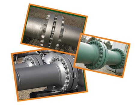
ASA 150 Standard Flange are widely used in USA and it defines the size, pressure rating and dimensions
ASA 150 flanges are widely used in the United States and adhere to the American National Standard Institute B16.5 standard. This standard outlines the size, pressure rating, and overall dimensions of flanges used for connecting pipes in various piping systems. Their widespread use ensures compatibility and reliability across different industries.
ASA 150 Standard Flange Application
- Power Generation
- Chemical Equipment
- Pulp and Paper Industry
- Gas Processing
- Heat Exchangers
- Sea Water Equipment
- Pharmaceuticals
- Off-Shore Oil Drilling Companies
- Condensers

ASA Flange Full Form
ASA Flange: American Standard Association Flange
ASA 150 vs ANSI 150
| Description | ANSI 150 | ASA 150 |
|---|---|---|
| Standard | American National Standards Institute | American Standard Association |
| Pressure Rating | #150 | #150 |
| Temperature Range | Standard temperature ranges based on materials | Vary based on the design and material |
| Material | Carbon steel, Stainless steel, etc | Based on the application |
| Bolt Pattern | Defined bolt pattern with specific dimensions | Same as ANSI 150 |
| Gasket Dimensions | Standard dimensions | Same as ANSI 150 |
| Historical Context | Modern standard | Older standard |
ASA 150 LB flange Advantages
- Standard dimension
- Moderate pressures
- Simple installation
- Reduce errors
- Less expensive
- Simple maintenance
- ASME standards
- Excellent for medium temperature ranges
- Better sealing options
ASA 150 Flange Standard Disadvantages
- Limited pressure ratings
- Not suitable for high pressure
- Material limitations
- Require additional documentation
- Limited design
- Not be suitable for low or high temperature
Stainless Steel Soft Belt,Stainless Strip ,Flat Stainless Steel Belt,Titanium Material Coi
Ningbo Boss Metal Material Co., Ltd. , https://www.boss-metal.com
